- 您现在的位置:买卖IC网 > Sheet目录343 > MIC4422ZT (Micrel Inc)IC DRIVER MOSFET 9A LS TO-220-5
�� �
�
�MIC4421/4422�
�Applications� Information�
�Supply� Bypassing�
�Charging� and� discharging� large� capacitive� loads� quickly�
�requires� large� currents.� For� example,� charging� a� 10,000pF�
�load� to� 18V� in� 50ns� requires� 3.6A.�
�The� MIC4421/4422� has� double� bonding� on� the� supply� pins,�
�the� ground� pins� and� output� pins.� This� reduces� parasitic�
�lead� inductance.� Low� inductance� enables� large� currents� to�
�be� switched� rapidly.� It� also� reduces� internal� ringing� that� can�
�cause� voltage� breakdown� when� the� driver� is� operated� at� or�
�near� the� maximum� rated� voltage.�
�Internal� ringing� can� also� cause� output� oscillation� due� to�
�feedback.� This� feedback� is� added� to� the� input� signal� since� it�
�is� referenced� to� the� same� ground.�
�VS�
�Micrel,� Inc.�
�To� guarantee� low� supply� impedance� over� a� wide� frequency�
�range,� a� parallel� capacitor� combination� is� recommended� for�
�supply� bypassing.� Low� inductance� ceramic� disk� capacitors�
�with� short� lead� lengths� (<� 0.5� inch)� should� be� used.� A� 1μF� low�
�ESR� ?lm� capacitor� in� parallel� with� two� 0.1μF� low� ESR� ceramic�
�capacitors,� (such� as� AVX� RAM� Guard� ?� ),� provides� adequate�
�bypassing.� Connect� one� ceramic� capacitor� directly� between�
�pins� 1� and� 4.� Connect� the� second� ceramic� capacitor� directly�
�between� pins� 8� and� 5.�
�Grounding�
�The� high� current� capability� of� the� MIC4421/4422� demands�
�careful� PC� board� layout� for� best� performance.� Since� the�
�MIC4421� is� an� inverting� driver,� any� ground� lead� impedance�
�will� appear� as� negative� feedback� which� can� degrade� switching�
�speed.� Feedback� is� especially� noticeable� with� slow-rise� time�
�inputs.� The� MIC4421� input� structure� includes� about� 200mV�
�of� hysteresis� to� ensure� clean� transitions� and� freedom� from�
�oscillation,� but� attention� to� layout� is� still� recommended.�
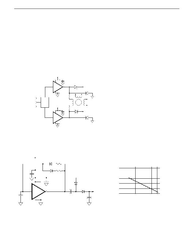
�?1� DRIV� E� S� IGNA� L�
�CONDUCTION� ANGLE�
�CONT� ROL� 0°� TO� 180°�
�CONDUCTION� ANGLE�
�CONTROL� 180°� TO� 360°�
�DRIVE�
�L� OGIC�
�MIC4451�
�VS�
�MIC4452�
�1μF�
�VS�
�?2�
�?1� M� ?3�
�1μF� VS�
�PHASE� 1� of� 3� PHASE� MOTOR�
�DRIVER� USING� MIC4420/4429�
�Figure� 5� shows� the� feedback� effect� in� detail.� As� the� MIC4421�
�input� begins� to� go� positive,� the� output� goes� negative� and�
�several� amperes� of� current� ?ow� in� the� ground� lead.� As� little�
�as� 0.05Ω� of� PC� trace� resistance� can� produce� hundreds� of�
�millivolts� at� the� MIC4421� ground� pins.� If� the� driving� logic� is�
�referenced� to� power� ground,� the� effective� logic� input� level� is�
�reduced� and� oscillation� may� result.�
�To� insure� optimum� performance,� separate� ground� traces�
�should� be� provided� for� the� logic� and� power� connections.� Con-�
�necting� the� logic� ground� directly� to� the� MIC4421� GND� pins�
�will� ensure� full� logic� drive� to� the� input� and� ensure� fast� output�
�switching.� Both� of� the� MIC4421� GND� pins� should,� however,�
�still� be� connected� to� power� ground.�
�Figure� 3.� Direct� Motor� Drive�
�+15�
�(x2)� 1N4448�
�0.1μF�
�50V�
�5.6� k?�
�560� ?�
�30�
�29�
�OUTPUT� VOLTAGE� vs� LOAD� CURRENT�
�1�
�+�
�1μF�
�50V�
�MKS2�
�BYV� 10� (x� 2)�
�28�
�27�
�12� ?� LINE�
�2�
�0.1μF�
�WIMA�
�MKS2�
�8�
�MIC4421�
�5�
�4�
�6,� 7� +�
�560μF� 50V�
�100μF� 50V�
�UNIT� E� D� CHE� MCON� S� X� E�
�+�
�26�
�25�
�0�
�50�
�100� 150� 200� 250� 300� 350�
�mA�
�Figure� 4.� Self� Contained� Voltage� Doubler�
�August� 2005�
�7�
�M9999-081005�
�发布紧急采购,3分钟左右您将得到回复。
相关PDF资料
MIC4424YWM
IC DRIVER MOSFET 3A DUAL 16-SOIC
MIC4427YM
IC DRIVER MOSFET DUAL 1.5A 8SOIC
MIC4451ZT
IC DRIVER MOSFET 12A HS TO220-5
MIC4467YWM
IC DRIVER MOSF QUAD 1.2A 16-SOIC
MIC44F19YMME
IC MOSFET DRIVER 6A HS 8-MSOP
MIC4801YM
IC WHITE LED DVR 600MA 1CH 8SOIC
MIC4802YME
IC WHITE LED DVR 800MA 1CH 8SOIC
MIC4807BN
IC DRIVER 80V 8CH ADDRESS 18-DIP
相关代理商/技术参数
MIC4423
制造商:MICREL 制造商全称:Micrel Semiconductor 功能描述:Dual 3A-Peak Low-Side MOSFET Driver Bipolar/CMOS/DMOS Process
MIC4423_05
制造商:MICREL 制造商全称:Micrel Semiconductor 功能描述:Dual 3A-Peak Low-Side MOSFET Driver
MIC4423_11
制造商:MIC 制造商全称:MIC GROUP RECTIFIERS 功能描述:Dual 3A-Peak Low-Side MOSFET Driver Bipolar/CMOS/DMOS Process
MIC4423BM
功能描述:IC DRIVER MOSFET 3A DUAL 8-SOIC RoHS:否 类别:集成电路 (IC) >> PMIC - MOSFET,电桥驱动器 - 外部开关 系列:- 标准包装:50 系列:- 配置:高端 输入类型:非反相 延迟时间:200ns 电流 - 峰:250mA 配置数:1 输出数:1 高端电压 - 最大(自引导启动):600V 电源电压:12 V ~ 20 V 工作温度:-40°C ~ 125°C 安装类型:通孔 封装/外壳:8-DIP(0.300",7.62mm) 供应商设备封装:8-DIP 包装:管件 其它名称:*IR2127
MIC4423BM TR
功能描述:IC DRIVER MOSFET 3A DUAL 8-SOIC RoHS:否 类别:集成电路 (IC) >> PMIC - MOSFET,电桥驱动器 - 外部开关 系列:- 标准包装:50 系列:- 配置:高端 输入类型:非反相 延迟时间:200ns 电流 - 峰:250mA 配置数:1 输出数:1 高端电压 - 最大(自引导启动):600V 电源电压:12 V ~ 20 V 工作温度:-40°C ~ 125°C 安装类型:通孔 封装/外壳:8-DIP(0.300",7.62mm) 供应商设备封装:8-DIP 包装:管件 其它名称:*IR2127
MIC4423BN
功能描述:IC DRIVER MOSFET 3A DUAL 8DIP RoHS:否 类别:集成电路 (IC) >> PMIC - MOSFET,电桥驱动器 - 外部开关 系列:- 标准包装:50 系列:- 配置:高端 输入类型:非反相 延迟时间:200ns 电流 - 峰:250mA 配置数:1 输出数:1 高端电压 - 最大(自引导启动):600V 电源电压:12 V ~ 20 V 工作温度:-40°C ~ 125°C 安装类型:通孔 封装/外壳:8-DIP(0.300",7.62mm) 供应商设备封装:8-DIP 包装:管件 其它名称:*IR2127
MIC4423BWM
功能描述:功率驱动器IC 3A Dual High Speed MOSFET Driver
RoHS:否 制造商:Micrel 产品:MOSFET Gate Drivers 类型:Low Cost High or Low Side MOSFET Driver 上升时间: 下降时间: 电源电压-最大:30 V 电源电压-最小:2.75 V 电源电流: 最大功率耗散: 最大工作温度:+ 85 C 安装风格:SMD/SMT 封装 / 箱体:SOIC-8 封装:Tube
MIC4423BWM TR
功能描述:功率驱动器IC 3A Dual High Speed MOSFET Driver
RoHS:否 制造商:Micrel 产品:MOSFET Gate Drivers 类型:Low Cost High or Low Side MOSFET Driver 上升时间: 下降时间: 电源电压-最大:30 V 电源电压-最小:2.75 V 电源电流: 最大功率耗散: 最大工作温度:+ 85 C 安装风格:SMD/SMT 封装 / 箱体:SOIC-8 封装:Tube